Installation performed by:
Special Touch
Mansfield, OH
The owner has reported an improvement in power as well as an increase in fuel mileage. We have asked for further testing before posting the details for you.
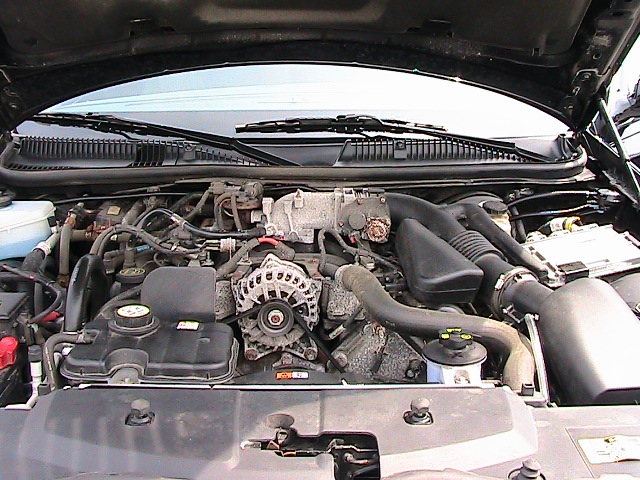
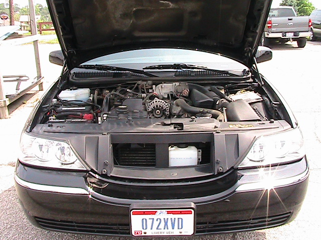
A view of the engine compartment.
It was a challenge to find room for the water supply tank.
Optimally, the tank needed to be located almost directly above the PEC Generator.
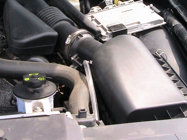
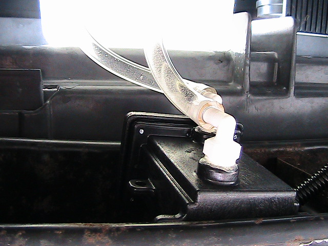
This is a view of the vapor hose entering the Air Inlet.
The vapor hose delivers the vapors, produced by the PEC generator, to the engine.
The hose enters the air inlet between the air filter and the MAF sensor (Mass Air Flow).
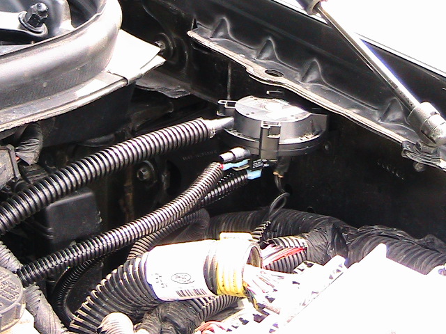
A view of the Go-no-Go Vacuum Switch.
The PEC Generator needs two things to happen for it to start working; 12vdc from the Ignition Switch and vacuum from the engine.
When the Ignition switch is turned on, it sends 12vdc to the Vacuum Switch.
When the engine is started, it creates a vacuum pressure that turns on the Vacuum Switch.
The Vacuum Switch sends 12vdc to the Power Relay that turns the generator on.
A loss of vacuum or Ignition battery turns the generator off.
This is a view of the 12vdc Power Relay and Fuse
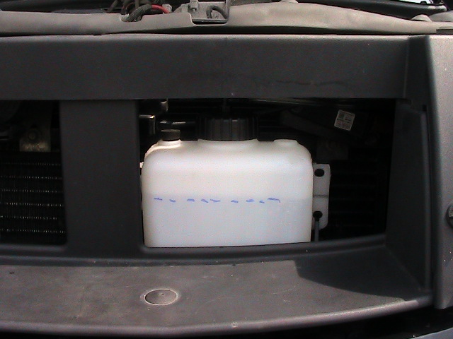
This is a view of the Water Supply Tank.
The white tank above the license plate.
The vapors from the PEC Generator get washed as they bubble through the water supply tank.
The tank contains a safety pressure blow off port in case there should ever be an engine backfire.
The job of the tank is to keep the PEC Generator full of water - circulate the water in the generator - and keep foam from entering the engines air way.
A close up of the water supply tank
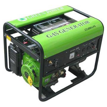
A view of the PEC Hydrogen Generator
The white area above the generator is the bottom of the water supply tank.
The bottom hose on the generator is the water return hose.
The top hose is the vapor hose that carries the hydrogen and oxygen vapors to the water supply tank.
"click an image to learn more"
Copyright � 2009 Power Emissions Control, a division of Z Tech, LLC. All rights reserved. Revised: 09/28/09. Web Author, daddyo44907